9.11 - Quick Reference
Module: Type III Low-Pressure Appliances
Covers: Sections 9.1–9.10
Regulatory and safety verification date: August 13, 2026
Use: Rapid review before the Module 9 Type III practice questions and later Universal certification review
1. Type III Scope and Low-Pressure Fundamentals
Type III certification applies to covered:
LOW-PRESSURE APPLIANCES
The current Section 608 low-pressure definition is based on refrigerant liquid-phase saturation pressure:
BELOW 45 psia AT 104°F
→ LOW-PRESSURE APPLIANCE
→ TYPE III
Representative low-pressure refrigerants introduced in this module include:
- R-11.
- R-113.
- R-123.
- R-245fa.
Important Boundaries
LOW-PRESSURE APPLIANCE
≠
every chiller
CENTRIFUGAL COMPRESSOR
≠
automatically Type III
LOW-PRESSURE APPLIANCE
≠
every point in the refrigeration circuit is always under vacuum
Type III classification depends on the refrigerant pressure category, not on:
- Chiller size.
- Compressor appearance.
- Building type.
- Whether the appliance is located in a machinery room.
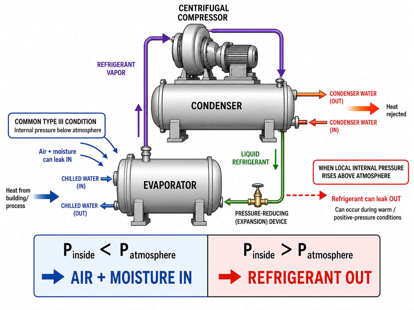
2. Pressure Direction and Leak Direction
A low-pressure chiller can operate below atmospheric pressure.
When:
Pinside < Patmosphere
the likely leak direction is:
AIR + MOISTURE
→ INTO THE CHILLER
When:
Pinside > Patmosphere
the possible leak direction is:
REFRIGERANT
→ OUT OF THE CHILLER
Exam Trap
Do not assume:
SHUTDOWN
→ entire chiller automatically positive
Leak direction depends on the local pressure difference at the leak location.
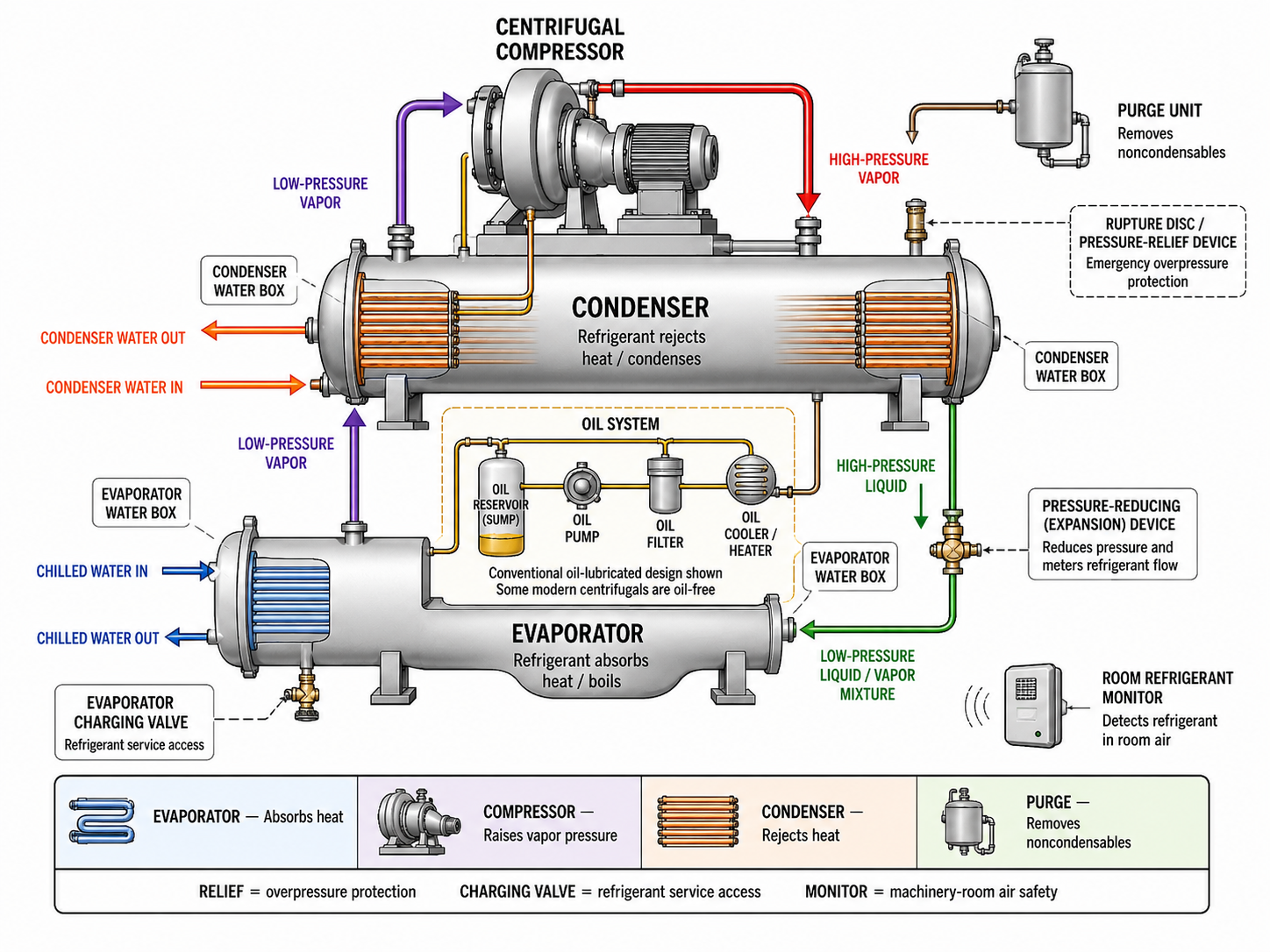
3. Low-Pressure Chiller Component Map
| Component | Main Type III Function / Reminder |
|---|---|
| Evaporator | Absorbs heat from chilled water; refrigerant boils |
| Centrifugal compressor | Receives refrigerant vapor and raises its pressure |
| Condenser | Rejects heat to condenser water; refrigerant condenses |
| Evaporator water box | Carries chilled water to/from evaporator tubes |
| Condenser water box | Carries condenser water to/from condenser tubes |
| Purge unit | Removes noncondensables while minimizing refrigerant loss |
| Rupture disc / relief device | Emergency overpressure protection |
| Evaporator charging valve | Type III centrifugal-chiller charging connection |
| Oil system | Lubrication system on applicable conventional chillers; refrigerant can dissolve in oil |
| Room refrigerant monitor | Detects refrigerant in machinery-room air |
High-Priority State Reminder
EVAPORATOR
→ refrigerant boils
COMPRESSOR
→ vapor in
→ higher-pressure vapor out
CONDENSER
→ refrigerant condenses
Water-Side Reminder
Water and refrigerant are normally separated by the heat-exchanger tube wall.
A tube failure can create:
WATER SIDE
↔
REFRIGERANT SIDE
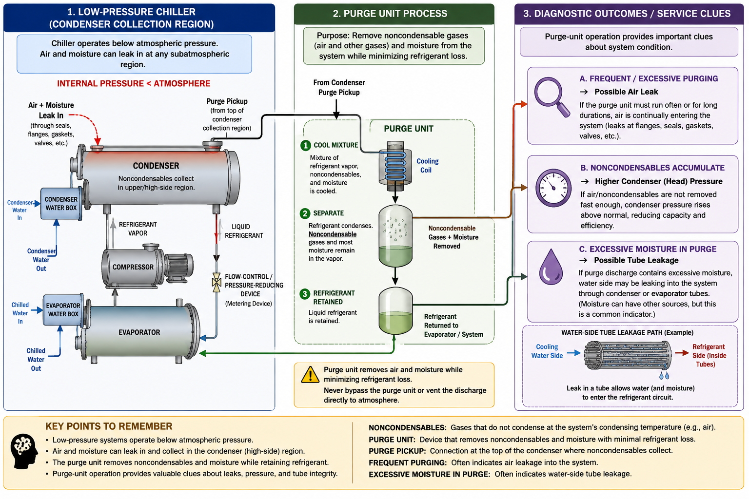
4. Air, Moisture, Noncondensables, and Purge Units
Why Air Enters
CHILLER PRESSURE BELOW ATMOSPHERE
+
LEAK
→
AIR + MOISTURE ENTER
Air that enters becomes a source of:
NONCONDENSABLES
Where Noncondensables Collect
For the traditional Type III exam model:
NONCONDENSABLES
→ collect near the upper / top condenser region
Purge-Unit Purpose
PURGE UNIT
→ removes noncondensables
→ minimizes refrigerant loss
A purge stream can contain:
REFRIGERANT VAPOR
+
AIR / NONCONDENSABLES
The purge unit separates them so that refrigerant is retained or returned while noncondensables are removed.
Diagnostic Clues
FREQUENT / EXCESSIVE PURGING
→ POSSIBLE AIR LEAK
NONCONDENSABLES
→ POSSIBLE HIGHER CONDENSER / HEAD PRESSURE
EXCESSIVE MOISTURE IN PURGE
→ POSSIBLE TUBE LEAK
Important Caution
HIGH HEAD PRESSURE
≠
automatic proof of noncondensables
Other heat-rejection problems can also raise condenser pressure.
PURGE UNIT
→ removes noncondensables
≠
repairs the leak
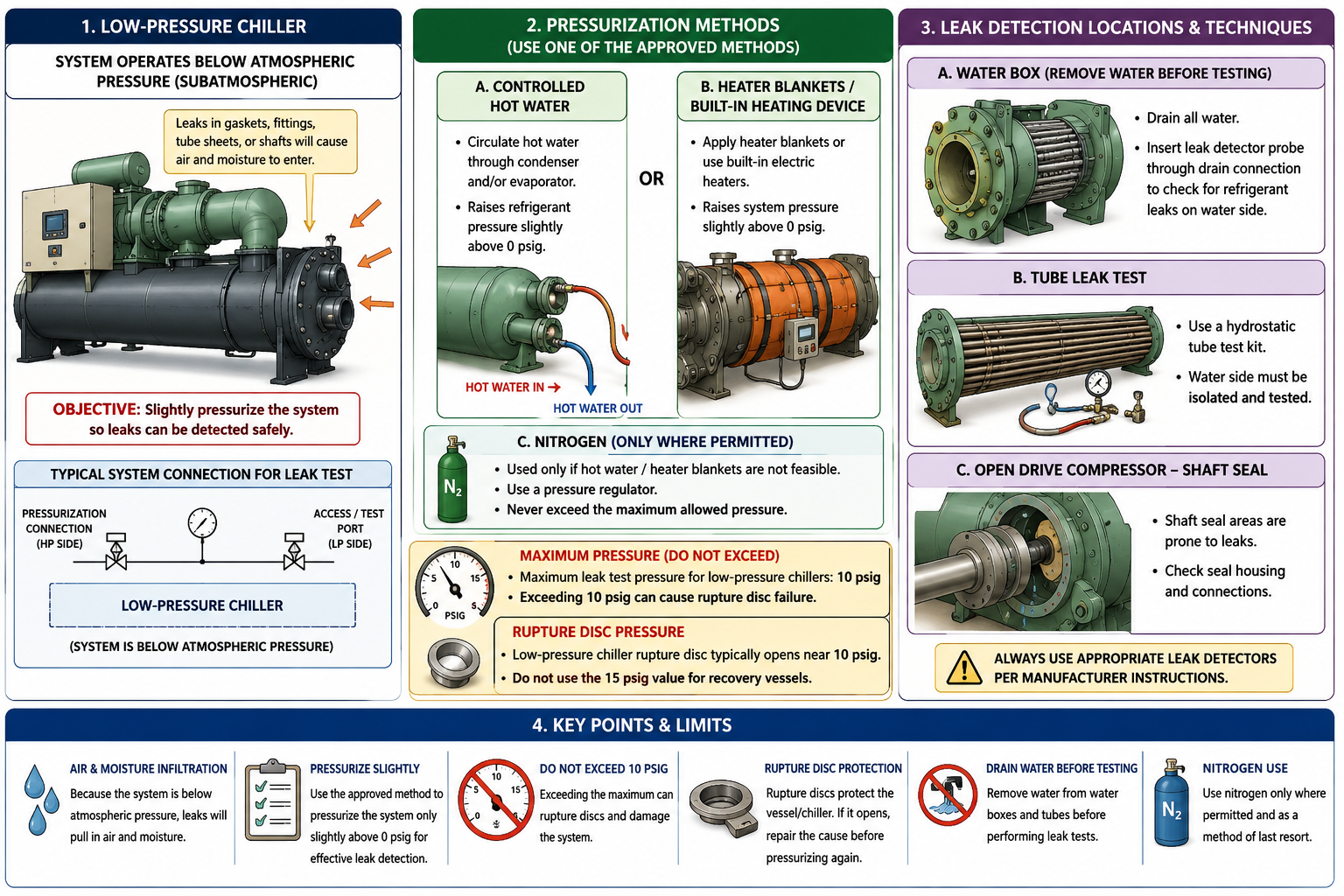
5. Low-Pressure Leak Detection and Pressurization
Low-pressure operation can draw air inward, so an outward refrigerant leak can be difficult to locate while the chiller is under vacuum.
For leak checking, the Type III sequence taught in this module is:
APPROVED HEAT / HOT WATER FIRST
→
REGULATED NITROGEN SECOND where permitted
Heat-based methods can include:
- Controlled hot water.
- Approved built-in pressurization/heating equipment.
- Approved heater blankets where applicable.
Leak-Test Pressure
For this module’s Type III exam preparation:
LOW-PRESSURE CHILLER LEAK-TEST MAXIMUM
→ 10 psig
10 psig is a:
MAXIMUM
not a required target for every leak test.
Never Use
OXYGEN
or:
COMPRESSED AIR
for refrigerant-system pressure testing.
Important Distinction
LEAK TEST
→ up to the applicable test limit
is different from:
QUALIFYING NON-MAJOR OPENING
→ no higher than 0 psig
The two procedures must not be mixed.
6. High-Priority Type III Leak Locations and Methods
| Condition / Location | Quick Reference |
|---|---|
| General outward refrigerant leak | Pressurize using approved method; use compatible leak detector |
| Water-box leak check | Remove water first, then use detector through the drain opening as taught in the Type III exam model |
| Suspected tube leak | Use the appropriate hydrostatic tube-test method / equipment |
| Open-drive compressor | Check the shaft seal as a high-priority leak location |
| Frequent purge operation | Possible air infiltration |
| Excessive purge moisture | Possible tube / water-side leakage |
Leak Direction Reminder
UNDER VACUUM
→ air may leak IN
POSITIVE PRESSURE
→ refrigerant may leak OUT
7. Type III Recovery Sequence
The core recovery sequence is:
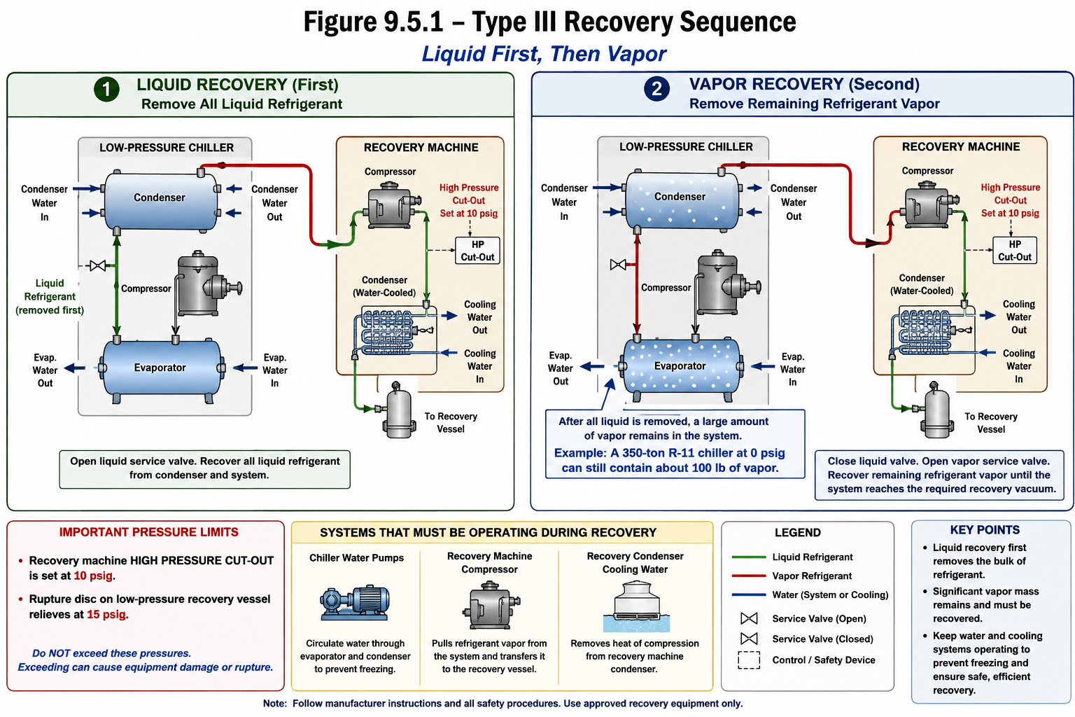
1. RECOVER BULK LIQUID FIRST
↓
2. RECOVER REMAINING VAPOR
↓
3. CONTINUE TO REQUIRED ENDPOINT
↓
4. WAIT / CHECK FOR PRESSURE REBOUND
Why Liquid First?
LIQUID
→ much greater mass per unit volume
→ faster bulk refrigerant removal
Why Vapor Recovery Is Still Required
NO BULK LIQUID
≠
NO REFRIGERANT
A large low-pressure chiller can still contain a substantial vapor mass after liquid recovery.
Classic Exam Example
350-ton R-11 chiller
at 0 psig
→ about 100 lb of vapor can still remain
after bulk liquid is removed
This is a representative exam example, not a universal engineering value for every chiller.
8. Recovery-Machine Relationships
During the classic normal Type III recovery condition:
CHILLER SYSTEM WATER PUMPS
→ ON
RECOVERY COMPRESSOR
→ ON
RECOVERY CONDENSER COOLING WATER
→ ON
Vapor-Recovery Path
CHILLER VAPOR
→ RECOVERY COMPRESSOR
→ RECOVERY-MACHINE CONDENSER
→ RECOVERY VESSEL
Recovery Condenser
The recovery-machine condenser rejects heat from compressed refrigerant.
For the traditional water-cooled Type III recovery arrangement:
COOLING WATER FLOW ↓
→ HEAT REJECTION ↓
→ RECOVERY DISCHARGE PRESSURE ↑
→ HIGH-PRESSURE CUTOUT MAY TRIP
9. Traditional Type III Recovery-Equipment Values
Keep the component and value together.
| Component / Procedure | Type III Exam-Preparation Value |
|---|---|
| Low-pressure chiller leak-test maximum | 10 psig |
| Recovery-unit high-pressure cutout | 10 psig |
| Low-pressure recovery-vessel rupture disc | 15 psig |
Do Not Confuse the Two 10-psig Values
10 psig
→ leak-test maximum
and:
10 psig
→ recovery-unit high-pressure cutout
are associated with different procedures.
Do Not Transfer 15 psig to the Chiller
15 psig
→ traditional LOW-PRESSURE RECOVERY-VESSEL rupture-disc value
It is not a universal centrifugal-chiller rupture-disc rating.
Actual chiller pressure-relief ratings are equipment-specific.
10. Freeze Prevention During Recovery
As refrigerant pressure falls:
PRESSURE ↓
→ SATURATION TEMPERATURE ↓
→ REMAINING REFRIGERANT BOILS AT LOWER TEMPERATURE
→ HEAT IS ABSORBED
→ FREEZE RISK ↑
Current Type III Principle
DURING REFRIGERANT EVACUATION
→ CIRCULATE OR REMOVE WATER
→ PREVENT FREEZING
Normal Water-Tight Chiller
When water circulation is the approved procedure:
MOVING WATER
→ brings heat to cold tube surfaces
→ reduces local freeze risk
Important Caution
PUMP MOTOR ON
≠
proof of adequate water flow
Verify actual flow according to the equipment procedure.
11. Suspected Tube Leak: Special Water-Side Rule
A suspected tube leak changes the normal water-management approach.
If the refrigerant side is under vacuum and the water side remains pressurized:
PWATER > PREFRIGERANT
→ WATER CAN ENTER THROUGH FAILED TUBE
For the Type III exam-preparation condition:
SUSPECTED TUBE LEAK
→ DRAIN EVAPORATOR WATER SIDE
→ DRAIN CONDENSER WATER SIDE
→ THEN RECOVER ACCORDING TO APPROVED PROCEDURE
Do Not Apply Blindly
NORMAL RECOVERY
→ circulate or remove water as required
SUSPECTED TUBE LEAK
→ do not blindly keep circulating water
12. Refrigerant Dissolved in Oil
Refrigerant can remain:
DISSOLVED IN COMPRESSOR OIL
even after bulk liquid and much of the free vapor have been recovered.
Oil Heating
Current Type III exam knowledge:
HEAT OIL TO 130°F
BEFORE REMOVING IT
TO MINIMIZE REFRIGERANT RELEASE
Heating helps:
REFRIGERANT LEAVE OIL
→ ENTER VAPOR SPACE
→ BECOME AVAILABLE FOR RECOVERY
Oil Foaming
SUDDEN PRESSURE DROP
→ dissolved refrigerant rapidly leaves oil
→ OIL FOAMING
Controlled temperature and pressure changes are important.
Field Rule
130°F
→ important Type III exam value
but:
ACTUAL OIL-HEATING PROCEDURE
→ manufacturer limits and approved service procedure
Some modern centrifugal chillers are oil-free; identify the actual machine design.
13. Current Oil-Change Pressure Rule
For an oil change, current § 82.156 permits the appliance or isolated portion to be:
EVACUATED OR PRESSURIZED
TO NO HIGHER THAN 5 psig
BEFORE OPENING
or the permitted system-receiver procedure may be used.
Keep the Values Separate
130°F
→ oil-heating exam value
5 psig MAX
→ oil-change opening / receiver pressure condition
25 mm Hg absolute
→ normal Type III Table 1 evacuation requirement
OIL REMOVED
≠
RECOVERY COMPLETE
14. Recharging Low-Pressure Systems
Correct Charging Connection
Current Type III exam relationship:
CENTRIFUGAL CHILLER
→ EVAPORATOR CHARGING VALVE
The outline’s lowest access point should be interpreted as the designated low evaporator refrigerant-side charging connection.
Do not use:
ANY PHYSICALLY LOW FITTING
unless it is actually the manufacturer-designated charging connection.
Initial Charge
DEEPLY EVACUATED LOW-PRESSURE CHILLER
→ VAPOR FIRST
→ LIQUID LATER
15. Why Vapor Is Charged First
If bulk liquid refrigerant enters a deep vacuum:
LIQUID
→ RAPID FLASH EVAPORATION
→ LATENT HEAT ABSORBED
→ STRONG LOCAL COOLING
→ WATER IN TUBES CAN FREEZE
Initial vapor charging instead causes:
VAPOR ADDED
→ PRESSURE ↑
→ SATURATION TEMPERATURE ↑
→ FREEZE RISK ↓
Vapor-to-Liquid Transition
VAPOR FIRST
↓
raise pressure and saturation temperature
↓
establish safe condition
↓
CONTROLLED LIQUID CHARGING
There is no universal project-wide transition pressure.
Use the manufacturer-approved procedure.
16. Type III Required Evacuation Level
The current normal Section 608 Table 1 requirement for a low-pressure appliance is:
25 mm Hg ABSOLUTE
Both Recovery-Equipment Date Columns
Recovery/recycling equipment
BEFORE Nov. 15, 1993
→ 25 mm Hg absolute
Recovery/recycling equipment
ON / AFTER Nov. 15, 1993
→ 25 mm Hg absolute
Critical Date Trap
The November 15, 1993 date applies to:
RECOVERY / RECYCLING EQUIPMENT
not the:
CHILLER MANUFACTURE DATE
17. Type III Charge-Size Trap
For the normal low-pressure Table 1 row:
< 200 lb
→ 25 mm Hg absolute
≥ 200 lb
→ 25 mm Hg absolute
The 200-lb boundary changes some Type II evacuation rows, but it does not change the normal Type III low-pressure endpoint.
18. Understand the Unit: mm Hg Absolute
The current Type III requirement is:
25 mm Hg ABSOLUTE
not:
25 in. Hg VACUUM
Absolute-Pressure Reminder
0 mm Hg absolute
→ perfect vacuum
25 mm Hg absolute
→ current Type III normal Table 1 endpoint
~760 mm Hg absolute
→ standard atmosphere
Do not replace the regulatory value with a different unit unless a conversion is clearly identified as approximate.
19. Pressure-Rebound Check
After reaching the required recovery vacuum:
REACH ENDPOINT
↓
STOP / ISOLATE AS DIRECTED
↓
WAIT A FEW MINUTES
↓
OBSERVE PRESSURE
If Pressure Rises
Primary Type III refrigerant clues:
REMAINING LIQUID REFRIGERANT
or:
REFRIGERANT LEAVING OIL
During broader post-service vacuum diagnosis, also consider:
- Moisture.
- Outgassing.
- Appliance leakage.
- Hose / service-setup leakage.
Exam Trap
PRESSURE RISE
≠
automatic proof of an external leak
and:
ONE MOMENTARY READING
AT 25 mm Hg absolute
≠
automatic proof recovery is complete
20. Major Repair
Current major maintenance, service, or repair includes removal of:
- Compressor.
- Condenser.
- Evaporator.
- Auxiliary heat-exchange coil.
It also includes work that:
UNCOVERS AN OPENING
> 4 in² OF FLOW AREA
FOR > 15 min
Memory Rule
MAJOR REPAIR
→ named major component removal
OR
→ >4 in² opening exposed >15 min
For a normal non-leaking low-pressure appliance undergoing major repair:
TABLE 1
→ 25 mm Hg absolute
unless another specific regulatory exception applies.
21. Qualifying Non-Major Opening
A limited current exception applies only when the regulatory conditions are satisfied.
For a qualifying low-pressure non-major opening:
PRESSURIZE
TO NO HIGHER THAN 0 psig
BEFORE OPENING
Important
NON-MAJOR
≠
automatically 0 psig
The complete § 82.156 conditions must be satisfied.
The permitted pressurization method also depends on refrigerant boiling-point conditions.
Do not interpret nitrogen as universally permitted for every qualifying non-major opening.
22. Leaking Appliance: Lowest Attainable Level
If a leak prevents the normal Table 1 level from being reached, or if deeper evacuation would substantially contaminate recovered refrigerant:
ISOLATE LEAKING
FROM NON-LEAKING COMPONENTS
WHEREVER POSSIBLE
Then:
NON-LEAKING PORTION
→ 25 mm Hg absolute
and:
LEAKING PORTION
→ LOWEST ATTAINABLE
without substantially contaminating recovered refrigerant
→ NOT ABOVE 0 psig
Important
LEAK EXISTS
≠
recovery no longer required
A good-faith recovery effort still applies.
23. Type III Pressure / Temperature / Safety Numbers
Keep every number tied to its procedure.
| Number / Threshold | Meaning in Module 9 |
|---|---|
| <45 psia at 104°F | Current low-pressure appliance classification |
| 10 psig maximum | Type III low-pressure chiller leak-test exam-preparation value |
| 10 psig | Traditional low-pressure recovery-unit high-pressure cutout |
| 15 psig | Traditional low-pressure recovery-vessel rupture-disc value |
| 130°F | Current Type III oil-heating exam value before oil removal |
| ≤5 psig | Current oil-change pressure condition before opening / receiver procedure |
| 25 mm Hg absolute | Current normal low-pressure Table 1 evacuation requirement |
| ≤0 psig | Qualifying non-major opening limit and leaking-component upper boundary in their respective current exceptions |
| Nov. 15, 1993 | Recovery/recycling equipment manufacture/import date; Type III endpoint remains 25 mm Hg absolute on both sides |
| 200 lb | Does not change the normal low-pressure Table 1 endpoint |
| >4 in² for >15 min | Major-repair opening-size/time criterion |
| O₂ <19.5% | OSHA oxygen-deficient atmosphere threshold |
Highest-Risk Number Confusion
10 psig
→ leak-test maximum
OR
→ recovery-unit cutout
depending on context
15 psig
→ recovery-vessel rupture disc
NOT universal chiller relief rating
5 psig
→ oil-change provision
NOT Type III final evacuation
0 psig
→ qualifying non-major / leaking-component exception boundary
NOT normal Type III Table 1 endpoint
25 mm Hg absolute
→ normal Type III Table 1 endpoint
24. Rupture Disc and Pressure-Relief Safety
Rupture Disc
RUPTURE DISC
→ EMERGENCY OVERPRESSURE PROTECTION
→ NON-RECLOSING
After rupture:
DISC MUST BE REPLACED
according to approved procedure
Do not:
- Use a rupture disc as a normal pressure regulator.
- Block or cap a required relief path.
- Substitute an arbitrary rating.
- Intentionally operate the device during a leak test.
Pressure-Relief Valve
PRESSURE-RELIEF VALVE
→ opens to relieve abnormal pressure
Many designs can reclose after pressure falls.
Required relief protection must remain effective.
25. Relief-Valve Arrangement Trap
Do not simply install two ordinary independent pressure-relief valves in series:
VESSEL
→ RELIEF VALVE 1
→ RELIEF VALVE 2
→ DISCHARGE
The downstream valve can restrict or interfere with the upstream relief path.
Do Not Overgeneralize
Approved engineered arrangements can include:
- Dual/changeover relief valves.
- Rupture-disc / pressure-relief-valve combinations.
Therefore:
TWO ORDINARY RELIEF VALVES
IN SIMPLE SERIES
→ NOT PROPER REDUNDANCY
but:
APPROVED ENGINEERED RELIEF COMBINATION
→ follow code / listing / manufacturer design
26. Machinery-Room Refrigerant Detection and Ventilation
Refrigerant Monitor
REFRIGERANT MONITOR
→ measures refrigerant in room air
It is not:
CHILLER PRESSURE SENSOR
Oxygen Monitor
OXYGEN MONITOR
→ measures oxygen concentration
The two instruments answer different questions.
Alarm / Ventilation Relationship
REFRIGERANT DETECTED
→ ALARM / VENTILATION RESPONSE
→ PERSONNEL FOLLOW EMERGENCY PROCEDURE
Important Caution
VENTILATION FAN ON
≠
AUTOMATICALLY SAFE TO ENTER
Atmospheric conditions must be evaluated according to the applicable procedure.
27. Toxicity, Oxygen Deficiency, and Confined Spaces
High-priority OSHA value:
O₂ < 19.5% BY VOLUME
→ OXYGEN-DEFICIENT ATMOSPHERE
Do Not Confuse
LOW-PRESSURE REFRIGERANT
≠
LOW-TOXICITY REFRIGERANT
Machinery Room
MACHINERY ROOM
≠
automatically an OSHA confined space
Evaluate the actual space against the confined-space criteria.
Possible Type III service locations that may require evaluation include:
- Pits.
- Vaults.
- Vessels.
- Certain water boxes.
- Below-grade enclosures.
A hazardous atmosphere can exist even where the space does not meet the confined-space definition.
28. Water-Side Safety
Stored Pressure
PUMP OFF
≠
ZERO WATER PRESSURE
Possible pressure sources include:
- Static head.
- Trapped pressure.
- Expansion tanks.
- Building pressure.
- Pump discharge.
- Thermal expansion.
Water-Box Service Sequence
ISOLATE
↓
CONTROL APPLICABLE HAZARDOUS ENERGY
↓
RELIEVE STORED PRESSURE
↓
DRAIN / VENT AS REQUIRED
↓
VERIFY SAFE CONDITION
↓
OPEN
Do not loosen water-box cover bolts to use the cover as a pressure-relief device.
Heavy Covers
Large water-box covers can require:
- Rated hoist.
- Lifting fixture.
- Rigging.
- Mechanical support.
- Manufacturer lifting points.
Plan the lift before the final bolts are removed.
29. Current Machinery-Room Code Review
For exam preparation, know the Type III machinery-room safety concepts.
For actual design or service compliance, check:
CURRENT PUBLISHED SAFETY STANDARD
+
LOCALLY ADOPTED CODE
+
AUTHORITY HAVING JURISDICTION (AHJ)
+
EQUIPMENT LISTING
+
MANUFACTURER INSTRUCTIONS
+
EMPLOYER SAFETY PROCEDURE
The module’s current-code review identifies:
ANSI/ASHRAE Standard 15-2024
and:
ANSI/ASHRAE Standard 34-2024
as the current published ASHRAE editions.
Important
CURRENT PUBLISHED EDITION
≠
automatically the legally adopted edition everywhere
Local adoption and amendments control enforceability.
30. Highest-Priority Type III Distinctions
| Do Not Confuse | Correct Distinction |
|---|---|
| Low-pressure appliance vs low side of a Type II appliance | Type III is a regulatory appliance pressure category |
| psia vs psig | Low-pressure classification uses psia |
| Air leak vs refrigerant leak direction | Below atmosphere → air/moisture in; above atmosphere → refrigerant can leak out |
| Purge unit vs recovery machine | Purge removes noncondensables; recovery machine removes refrigerant from appliance |
| Frequent purging vs repaired leak | Frequent purge is a clue; purge does not repair the leak |
| 10 psig leak-test max vs 10 psig recovery cutout | Same number, different procedure |
| 15 psig recovery-vessel disc vs chiller relief rating | 15 psig is not a universal chiller rating |
| Normal water circulation vs suspected tube leak | Tube-leak condition can require draining water sides |
| Vapor first vs liquid first | Recovery: liquid first; charging: vapor first |
| 130°F vs 5 psig | Oil heating temperature vs oil-change pressure condition |
| 25 mm Hg absolute vs 25 in. Hg vacuum | Only 25 mm Hg absolute is the current Type III normal Table 1 value |
| Nov. 15, 1993 date | Recovery/recycling equipment date, not chiller date |
| <200 lb vs ≥200 lb | Does not change normal low-pressure Table 1 endpoint |
| Major vs qualifying non-major | Major normally uses Table 1; qualifying non-major may use ≤0 psig opening provision |
| Leaking vs non-leaking portions | Non-leaking → Table 1; leaking → lowest attainable ≤0 psig |
| Refrigerant detector vs oxygen monitor | Different measured quantities |
| Machinery room vs confined space | Machinery room is not automatically a confined space |
| Pump off vs zero water pressure | Stored/static pressure can remain |
31. Type III Rapid Service Decision Sequence
Use this as an exam-reasoning sequence.
Step 1 — Confirm Type III Scope
LOW-PRESSURE APPLIANCE?
→ <45 psia saturation pressure at 104°F
Step 2 — Identify the Service Condition
Is the task primarily:
- Leak detection?
- Recovery?
- Tube-leak work?
- Oil service?
- Recharging?
- Evacuation?
- Safety / machinery-room response?
Step 3 — Control Water-Side Condition
NORMAL RECOVERY
→ circulate or remove water as approved
SUSPECTED TUBE LEAK
→ drain water sides before recovery
Step 4 — Recover
LIQUID FIRST
→ VAPOR SECOND
Step 5 — Manage Oil Refrigerant
HEAT OIL AS REQUIRED
→ 130°F exam value
→ recover released refrigerant
Step 6 — Reach the Applicable Evacuation Condition
Normal low-pressure Table 1:
25 mm Hg absolute
Qualifying exceptions must be identified separately.
Step 7 — Wait and Observe
WAIT A FEW MINUTES
→ PRESSURE REBOUND?
If yes, determine whether:
- Refrigerant remains.
- Refrigerant is leaving oil.
- Moisture/outgassing is present.
- A leak exists.
Step 8 — Recharge
EVAPORATOR CHARGING VALVE
→ VAPOR FIRST
→ LIQUID LATER when approved
Step 9 — Restore Safety Systems
Confirm the applicable:
- Relief protection.
- Refrigerant monitoring.
- Ventilation.
- Water-side condition.
- Manufacturer controls.
32. Twenty Type III Facts to Know Before the Practice Tests
- Type III applies to low-pressure appliances.
- Current low-pressure classification is below 45 psia saturation pressure at 104°F.
- Below atmospheric pressure, a leak can draw air and moisture in.
- Air in the chiller becomes noncondensables.
- The purge unit’s primary purpose is to remove noncondensables while minimizing refrigerant loss.
- Frequent purging can indicate an air leak.
- Excessive purge moisture can indicate a tube leak.
- Type III leak checking uses approved heat first, then regulated nitrogen where permitted.
- The Type III low-pressure chiller leak-test maximum used in this course is 10 psig.
- Recover liquid first, then recover vapor.
- A large chiller can still contain substantial refrigerant vapor after all visible liquid is gone.
- During normal recovery, water must be circulated or removed to prevent freezing.
- If tube leakage is suspected, the Type III exam procedure calls for draining evaporator and condenser water sides before recovery.
- Oil should be heated to 130°F before removal for the current Type III exam topic.
- The oil-change opening / receiver pressure condition is no higher than 5 psig.
- Recharge through the evaporator charging valve.
- In deep vacuum, charge vapor before liquid.
- The current normal Type III evacuation requirement is 25 mm Hg absolute.
- After reaching the required recovery vacuum, wait a few minutes and watch for pressure rise.
- A machinery-room refrigerant monitor detects refrigerant in room air, while an oxygen monitor measures oxygen.
33. Essential Module 9 Figures
Use the existing Module 9 figures for rapid visual review:
-
Figure 9.1.1 - Low-Pressure Centrifugal Chiller
Review Type III centrifugal-chiller layout and inward/outward leak-direction concept. -
Figure 9.2.1 - Low-Pressure Chiller Components
Review evaporator, condenser, compressor, water boxes, purge unit, relief protection, charging valve, oil system, and room monitor. -
Figure 9.3.1 - Low-Pressure Purge Unit Process
Review air/moisture infiltration, noncondensable collection, purge separation, and diagnostic clues. -
Figure 9.4.1 - Low-Pressure Leak Test Setup
Review controlled pressurization and Type III leak-test relationships. -
Figure 9.5.1 - Type III Recovery Sequence
Review liquid-first recovery, vapor recovery, recovery-machine condenser, water management, and recovery-equipment protection values. -
Figure 9.9.1 is planned in Section 9.9 as the visual review of the current 25 mm Hg absolute evacuation requirement and principal Type III exceptions.
No New Quick-Reference Figure
No Figure 9.11.x is added because the governing Module 9 outline does not specify a quick-reference figure.
34. Final Type III Memory Sheet
TYPE III
→ LOW-PRESSURE APPLIANCES
LOW PRESSURE
→ <45 psia saturation pressure at 104°F
Pinside < Patmosphere
→ AIR + MOISTURE IN
PURGE UNIT
→ REMOVE NONCONDENSABLES
→ MINIMIZE REFRIGERANT LOSS
FREQUENT PURGING
→ POSSIBLE AIR LEAK
EXCESSIVE PURGE MOISTURE
→ POSSIBLE TUBE LEAK
LEAK TEST
→ APPROVED HEAT FIRST
→ NITROGEN SECOND where permitted
→ MAX 10 psig
RECOVERY
→ LIQUID FIRST
→ VAPOR SECOND
NORMAL RECOVERY
→ CIRCULATE OR REMOVE WATER
→ PREVENT FREEZING
SUSPECTED TUBE LEAK
→ DRAIN EVAPORATOR + CONDENSER WATER SIDES
RECOVERY-UNIT CUTOUT
→ 10 psig
RECOVERY-VESSEL RUPTURE DISC
→ 15 psig
OIL
→ HEAT TO 130°F BEFORE REMOVAL
OIL CHANGE
→ NO HIGHER THAN 5 psig
CHARGING CONNECTION
→ EVAPORATOR CHARGING VALVE
DEEPLY EVACUATED CHILLER
→ VAPOR FIRST
→ LIQUID LATER
TYPE III TABLE 1
→ 25 mm Hg ABSOLUTE
BEFORE / AFTER NOV. 15, 1993 RECOVERY EQUIPMENT
→ SAME 25 mm Hg ABSOLUTE
<200 lb / ≥200 lb
→ SAME 25 mm Hg ABSOLUTE
QUALIFYING NON-MAJOR
→ NO HIGHER THAN 0 psig BEFORE OPENING
LEAKING PORTION
→ LOWEST ATTAINABLE
→ ≤0 psig
ENDPOINT REACHED
→ WAIT A FEW MINUTES
→ WATCH FOR PRESSURE REBOUND
RUPTURE DISC
→ EMERGENCY PROTECTION
→ NON-RECLOSING
TWO ORDINARY RELIEF VALVES
→ DO NOT SIMPLY INSTALL IN SERIES
REFRIGERANT MONITOR
→ REFRIGERANT IN ROOM AIR
OXYGEN MONITOR
→ OXYGEN CONCENTRATION
O₂ <19.5%
→ OXYGEN-DEFICIENT ATMOSPHERE
MACHINERY ROOM
≠ AUTOMATICALLY A CONFINED SPACE
PUMP OFF
≠ ZERO WATER PRESSURE
References
Current Regulatory and EPA Sources
-
Electronic Code of Federal Regulations, 40 CFR § 82.152 - Definitions, current low-pressure appliance definition and major-maintenance/service/repair definition. Verified August 13, 2026.
-
Electronic Code of Federal Regulations, 40 CFR § 82.156 - Proper Evacuation of Refrigerant From Appliances, current low-pressure Table 1 requirement, non-major opening provision, leaking-appliance exception, oil-change provision, and service-practice requirements. Verified August 13, 2026.
-
Electronic Code of Federal Regulations, 40 CFR § 82.161 - Technician Certification, current Type III certification scope. Verified August 13, 2026.
-
U.S. Environmental Protection Agency, Section 608 Test Topics, current Type III examination-topic framework for purge units, leak detection, recovery, freeze prevention, oil heating, recharging, evacuation, and machinery-room safety. Verified August 13, 2026.
-
U.S. Environmental Protection Agency, Stationary Refrigeration Service Practice Requirements, current service-practice summary. Verified August 13, 2026.
-
U.S. Environmental Protection Agency, Required Level of Evacuation of Appliances, current low-pressure evacuation table. Verified August 13, 2026.
Current Safety Sources
-
Occupational Safety and Health Administration, 29 CFR 1910.146 - Permit-Required Confined Spaces, confined-space definitions and oxygen-deficient-atmosphere threshold. Verified August 13, 2026.
-
Occupational Safety and Health Administration, 29 CFR 1910.147 - The Control of Hazardous Energy, hazardous-energy control requirements for applicable servicing. Verified August 13, 2026.
-
ASHRAE, current published ANSI/ASHRAE Standard 15-2024 and ANSI/ASHRAE Standard 34-2024 information used for the machinery-room current-code review in Section 9.10. Verified August 13, 2026.